| prev | home | next |
You may remember way back in part 5 that we did some simple calculations by hand to show that the classic racing line through a 90-degree right-hander is better than the either the line that hugs the inside or the line that hugs the outside of the corner. 'Better' means 'has lowest time.' The 'classic racing line' was, under the assumptions of that article, the widest possible inscribed line.
In this and the next instalment of The Physics of Racing, we raise the bar. Not only do we calculate the times for all lines through a corner, but we show a new kind of analysis for the exit, accounting for simultaneously accelerating and unwinding the steering wheel after the apex. This kind of analysis requires us to search for the lowest time because we cannot calculate it directly. We apply the approximation of the traction circle-subject of part 7-to stay within the capabilities of the car. We also model a more complex segment than in part 5, including an all-important exit chute where we take advantage of improved corner-exit speed. This style of analysis applies directly to computer simulation that we now have in progress in other continuing threads of The Physics of Racing.
The whole point of this analysis is to back up the old mantra: "slow-in, fast-out." We will find that the quickest way through the whole segment does not include the fastest line around the corner. Rather, we get the lowest overall time by cornering more slowly so we can get back on the gas earlier. It's always tempting to corner a little faster, but it frequently does not pay off in the context of the rest of the track.
This analysis is sufficiently long that it will take two instalments of this series. In this, the first instalment, we do exact calculations on a dummy line, which is the actual line we will drive up to the apex, but just a reference line after the apex. In the next instalment, we improve on the dummy line by accelerating and unwinding, predicting the times for a line we would actually drive, but entailing some small inexactitude.
Let's first describe the track segment. Imagine an entry straight of 650 feet, connected to a 180-degree left-hander with outer radius 200 feet and inner radius 100 feet, connected to an exit chute of 650 feet. In the following sketch, we show the segment twice with different lines. The line on the left contains the widest possible inscribed cornering radius, and therefore the greatest possible cornering speed. The sketch on the right shows the line with the lowest overall time. Although its cornering speed is slower than in the line on the left, it includes a lengthy acceleration and unwinding phase on exit that more than makes up for it.
|
|
|
| Line with Fastest Cornering Speed |
Line with Lowest Overall Time |
Note that both lines begin on the extreme right-hand side of the entry straight. Such will be a feature of every corner we analyse. Lines that begin elsewhere across the entry straight may be valid in scenarios like passing. However, we focus here on lines that are more obvious candidates for lowest times. Also, throughout, we ignore the width of the car, working with the 'bicycle line'. If we were including the width, w, of the car, we would get the same final results on a track with outer radius of 200 + w / 2 feet and inner radius of 100 - w / 2 feet.
First, we compute exact times where we can on the course: the entry straight, the braking zone, and the corner up to the apex. To have a concrete baseline for comparison, we also do a 'suboptimal' exit computation-the dummy line-that includes completing the corner without unwinding and then running down the exit chute dead straight somewhere in the middle of the track. In the next instalment of The Physics of Racing, we compare the dummy line to the more sophisticated exit that includes simultaneously accelerating and unwinding to use up the entire width of the track in the exit chute.
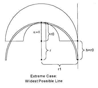
Let us enter the segment in the right-hand chute at 100 mph = 146.667 fps (feet per second). We want the total times for a number of different cornering radii between two extremes. The largest extreme is a radius of 200 feet, which is the same as the radius of the outer margin of the track. It should be obvious that it is not possible to drive a circle with a radius greater than 200 feet and still stay on the track. This extreme is depicted in the following sketch:

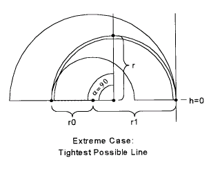
We take the opportunity, here, to define a number of parameters that will serve throughout. First, let us call the radius of the outer edge of the track r1; this is obviously 200 feet, but, by giving it a symbolic name, we retain the option of changing its numeric value some other time. Likewise, let's call the radius of the inner circle r0, now 100 feet. Let's use the symbol r to denote the radius of the inscribed circle we intend to drive. In the extreme case of the widest possible line, r is the same as r1, namely, 200 feet. In the other extreme case, that of the tightest inscribed circle, r is 150 feet, as shown in the following sketch:

We're now ready to discuss the two remaining parameters you may have noticed:
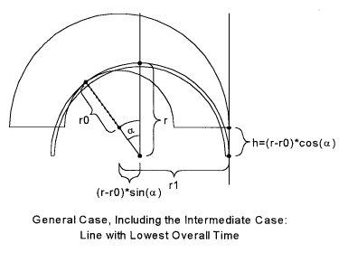
h and ![]() (Greek letter alpha). Consider the following figure illustrating the
general case:
(Greek letter alpha). Consider the following figure illustrating the
general case:

h indicates the point where we must be done with braking. More
precisely, h is the distance of the turn-in point below the
geometric start of the corner. Its value, by inspection, is (r - r0) cos
![]() .
.
![]() is the
angle past the geometric top where the inscribed circle-the driving line-apexes
the inner edge of the track. We see two values for the horizontal distance
between the centre of the inscribed circle and the centre of the inner edge, and
those values are (r - r0) sin
is the
angle past the geometric top where the inscribed circle-the driving line-apexes
the inner edge of the track. We see two values for the horizontal distance
between the centre of the inscribed circle and the centre of the inner edge, and
those values are (r - r0) sin
![]() and
r1 - r. Their equality allows us to solve for
and
r1 - r. Their equality allows us to solve for
![]() :
:
![]()
The following table shows numeric values of h and
![]() for a number of
inscribed radii (Note that if we varied r0 and r1 we would have a
much larger 'book' of values to show. For now, we'll just vary r.):
for a number of
inscribed radii (Note that if we varied r0 and r1 we would have a
much larger 'book' of values to show. For now, we'll just vary r.):
|
There are a couple of interesting things to notice about these numbers.
First, they match up with the visually obvious values of h = 0,
![]() = 90
and h = 100,
= 90
and h = 100, ![]() = 0 when r = 150,
r = 200 respectively. This is a good check that we haven't
made a mistake. Secondly,
= 0 when r = 150,
r = 200 respectively. This is a good check that we haven't
made a mistake. Secondly,
![]() changes
very rapidly with corner radius, and this fact has major ramifications on
driving line. By driving a line just one foot larger than the minimum, one
is able to apex more than fifteen degrees later!
changes
very rapidly with corner radius, and this fact has major ramifications on
driving line. By driving a line just one foot larger than the minimum, one
is able to apex more than fifteen degrees later!
With these data, we're now equipped to compute all the times up to the apex
and beyond. First, let's compute the speed in the corner by assuming that our
car can corner at 1g = 32.1 ft / s2
= v2 / r,
giving us ![]() .
We express all speeds in miles per hour, but other lengths in
feet. We won't take the time and space to write out all the conversions
explicitly, but just remind ourselves once and for all that there are 22 feet
per second for every 15 miles per hour.
.
We express all speeds in miles per hour, but other lengths in
feet. We won't take the time and space to write out all the conversions
explicitly, but just remind ourselves once and for all that there are 22 feet
per second for every 15 miles per hour.
Now that we have the maximum cornering speed, we can compute how much braking
distance we need to get down to that speed from 100 mph. Let's assume that our
car can brake at 1g also. We know that braking causes us to lose a little
velocity for each little increment of time. Precisely, dv / dt = g.
However, we need to understand how the velocity changes with distance, not with
time. Recall that dx / dt = v,
dt = dx / v, so we get dx = vdv / g.
Those who remember differential and integral calculus will immediately see that
![]() is
the required formula for braking distance. In any event, the braking distance
goes as the square of the speed, that is, like the kinetic energy, and that's
intuitive. However, there's a factor of two in the numerator that's easy to miss
(the origin of this factor is in the calculus, where we compute limit
expressions like
is
the required formula for braking distance. In any event, the braking distance
goes as the square of the speed, that is, like the kinetic energy, and that's
intuitive. However, there's a factor of two in the numerator that's easy to miss
(the origin of this factor is in the calculus, where we compute limit
expressions like ![]() ).
).
We next subtract the braking distance from the entry straight, and also subtract h, to give us the distance in which we can go at 100 mph, top speed, before the braking zone.
Now, we need the time spent braking, and that's easy:
![]() . All the
other times are easy to compute, so here are the times for a variety of
cornering lines up to the apices (or apexes for those who aren't Latin
majors):
. All the
other times are easy to compute, so here are the times for a variety of
cornering lines up to the apices (or apexes for those who aren't Latin
majors):
| Inscribed Corner Radius (ft) | Cornering speed @1g in mph | Braking Distance (ft) @1g from 100 mph | Straight Distance (ft) prior to braking | Time (sec) in straight @100 mph prior to braking | Time (sec) in braking zone | Time (sec) in corner prior to apex | Total time (sec) up to the apex |
|---|---|---|---|---|---|---|---|
| 150 | 47.24 | 261.11 | 388.89 | 2.652 | 2.418 | 6.802 | 11.872 |
| 152 | 47.55 | 260.11 | 369.89 | 2.522 | 2.404 | 5.987 | 10.912 |
| 154 | 47.86 | 259.11 | 362.60 | 2.472 | 2.390 | 5.682 | 10.544 |
| 155 | 48.02 | 258.61 | 359.77 | 2.453 | 2.382 | 5.566 | 10.401 |
| 160 | 48.79 | 256.11 | 349.17 | 2.381 | 2.347 | 5.144 | 9.872 |
| 170 | 50.29 | 251.11 | 335.64 | 2.288 | 2.278 | 4.641 | 9.208 |
| 180 | 51.75 | 246.11 | 326.43 | 2.226 | 2.212 | 4.325 | 8.762 |
| 190 | 53.16 | 241.11 | 319.45 | 2.178 | 2.147 | 4.099 | 8.424 |
| 200 | 54.55 | 236.11 | 313.89 | 2.140 | 2.083 | 3.927 | 8.150 |
At first glance, it appears that the widest line is a huge winner, but
we must realize that these times include only driving up to the apex, and that
is far earlier on the widest line, where ![]() = 0. Suppose we continued driving all
the way around the corner at constant speed and then accelerated out the exit
chute at 0.5g? This is the dummy line. We won't really drive this line
after the apex, but discuss it nonetheless to provide a reference time. It's
very easy to compute and provides a foundational intuition for the more advanced
exit computation to follow in the next instalment:
= 0. Suppose we continued driving all
the way around the corner at constant speed and then accelerated out the exit
chute at 0.5g? This is the dummy line. We won't really drive this line
after the apex, but discuss it nonetheless to provide a reference time. It's
very easy to compute and provides a foundational intuition for the more advanced
exit computation to follow in the next instalment:
| Inscribed Corner Radius (ft) | Total time (sec) up to the apex | Time (sec) in corner after apex | Time for entrance and complete corner | Exit speed from chute (mph) @ g/2 accel | Time in exit chute (sec) | Combined segment time | Combined post-apex time and exit-chute time |
|---|---|---|---|---|---|---|---|
| 150 | 11.872 | 0.000 | 11.872 | 109.091 | 5.670 | 17.541 | 5.670 |
| 152 | 10.912 | 0.860 | 11.773 | 107.857 | 5.528 | 17.301 | 6.388 |
| 154 | 10.544 | 1.209 | 11.754 | 107.422 | 5.460 | 17.213 | 6.669 |
| 155 | 10.401 | 1.348 | 11.750 | 107.260 | 5.430 | 17.180 | 6.779 |
| 160 | 9.872 | 1.881 | 11.753 | 106.697 | 5.308 | 17.061 | 7.189 |
| 170 | 9.208 | 2.600 | 11.808 | 106.101 | 5.116 | 16.924 | 7.716 |
| 180 | 8.762 | 3.126 | 11.888 | 105.806 | 4.955 | 16.844 | 8.082 |
| 190 | 8.424 | 3.556 | 11.980 | 105.666 | 4.813 | 16.792 | 8.369 |
| 200 | 8.150 | 3.927 | 12.077 | 105.627 | 4.682 | 16.760 | 8.609 |
So, we see that, driving the dummy line, the widest line yields the slowest time from the entrance up through the complete semicircle, but the quickest overall time when the exit chute is included. The widest line has lower (better) times than the tightest line in
The widest line has higher (worse) times by about a second in the circle itself because the wider circle is also longer. When the balances are all added up, the widest line is about eight tenths quicker than the tightest line, but it's all because of the effects of the corner on the straights before and after.
Recall once again that the dummy line is not a line we would actually drive after the apex. But, with that as a framework, we're in position to introduce the next improvement. Everything we do from here on improves just the post-apex portion of the corner and the exit chute. We will actually drive the dummy line up to the apex. So, from this point on, we need only look at the last column in the table above, where we are shocked to see that there are almost three seconds' spread from the slowest to the quickest way out. A good deal of this ought to be available for improvement by accelerating and unwinding.