Custom Search


There is wide agreement among many engine builders that the key to making power is the cylinder heads. This is a complex problem, as there are several components to the head, and they must all work together well. Just to make it more interesting, we have added durability issues to face with our air cooled configuration.
There are many different head castings, there's a good reference article in the Corsa Tech Guide which covers all the variations, but these can be boiled down to three basic head configurations:
Ok, I'm going to go out on a limb here - the turbo heads really aren't the ones you want for a turbo. Why? Because their open chambers are more likely to detonate. They are supposed to run a little cooler in stock form, but if you modify a set of 95 heads for proper squish (covered later), they are a better choice. Turbos in Stock or SP must use the stock heads, but for a street car or Prepared autocrosser, I'd highly recommend you consider a set of 95 heads.
Those 95 heads are a good choice for 110s as well, since we will be milling them a bit. So really your choices boil down to 95 heads or 140 heads. The 95 heads will have better port velocity, so they will do better at the low end. The big ports of the 140 work better up high, and they have the provision for the secondary carbs. If you are running under SP rules, the only way to get ported heads is to build a Yenko engine, which automatically means 140 heads. For a street car, a set of prepped 95 heads is possibly the best all around compromise for flexibility and durability. For a Prepared or Road Racer, you are going to be able to turn the most RPM's, and so make the most HP, with ported 140 heads.
The biggest durability issue with the Corvair head is dropped valve seats. It used to be that only 140s were a noted problem, but since all the heads are 30 or more years old, the problem has started to show up in small valve heads as well. There are a few ways to deal with the problem:
First, you can stake the seats. This involves using a staking tool which fits in the guide and has a little chisel shaped plunger, you go all the way around the seat and peen some aluminum over the seat. This technique has been debated a bit, but it's safe to say that it only really works on heads that haven't been overheated. When Corvairs were fairly new, or better yet if you started with a new pair of heads, this probably worked pretty well. But nowadays how can you be sure the heads haven't been overheated?
Method two is the preferred racer's technique - remove the old seats entirely and replace with a bigger, deeper seat. Expensive, but the best way to go. You can also fix a set of heads by welding then installing new seats, if you do this you should plan on doing all the seats, because the other ones are probably loose too.
Next is a method that involves somehow mechanically locking the seat in place, either by machining screw threads into the head and seat, or by machining the seat with a flange on the bottom, the seat would be installed then heliarced into place. Warren LeVeque offers the latter "sunken" seats as an option when he prepares heads.
Finally, Chuck Cromwell sent me this neat trick for installing set screws. He's had very good luck with this method, so I'm happy to put it up here. I will make two observations that may help you be successful. First, don't do this to a set of heads that have dropped a seat and you're trying to get by with replacing just one seat. Second, I'd suggest using a drill press to get the holes in straight, and perhaps practice on a junk head first.
Do this before you do a valve grind. With a 1/16th drill, drill a hole 1/4 inch deep into the aluminum right against the seat. Opposite that hole, drill another 1/16th hole 1/4 inch deep. That will be 2 holes 180 degrees from each other. Now drill both holes with a 1/8th drill, and finish with a 9/64ths drill, maintaining your 1/4 inch depth. Tap both holes with a 5/32nds (Note: a 10-32 should be the same size) bottom tap using plenty of oil on the tap. This will stop the aluminum from plugging the flutes. When you finish tapping the holes, flush them out with a good solvent such as brake cleaner, lacquer thinner, etc. Look in the holes and you will see threads in the side of the seats. Using (red) locktight on your screws, screw the screws down tight and let the locktite set up overnight. Then, using a dremel tool with the thinnest cut off blade, cut the screws off as close to the head as possible. Finally, use a grindstone in your dremel tool and grind the screws off flush with the head.
I've made quite a bit of mention of "ported" heads along the way. If you're not familiar with the term, the short explanation is that porting is improving the airflow of the port, and cleaning up imperfections in the casting. Like the other parts of the Corvair, the heads are a mass produced item, so the ports in the heads were designed to be made using simple molds, rather than the very best shape. Also, the casting porcess leaves a lot of imperfections in the surface of the port. Stan East wrote a great piece for FastVairs on porting heads, the specific example is a set of turbo heads, but the basic techniques apply to both turbos and normally aspirated engines. Here it is:
Porting and Polishing...You are running a turbo therefore do not...repeat DO NOT polish the intake and exhaust ports. On turbocharged vehicles the pressurized system benefits from the roughness of the port walls in keeping the air/gasoline mix atomized. You need an atomized mixture for good combustion.
You can however polish the combustion chamber, valves on the combustion chamber side and piston tops. This reduces carbon build up and makes cleaning the chambers easier the next time you service the motor. It also helps to reduce the heat transfer to these parts.
You can do minor porting on a turbocharged engine to allow the ports to work properly and remove the manufacturing flaws. Your porting should be restricted to removing the excess material around the exhaust and intake port valve guides and cleaning up the area directly under the valve seat. (Do not undercut in the port are below the valve seat). If there are blobs of metal in the ports where material has filled in or restricted part of the port then you can remove these as well, however on a turbo engine porting like a normally aspirated engine is a waste of time and hurts performance.
While you are doing porting work don't nick, cut or damage the valve seat or valve guide either internally or externally. A damaged valve seat requires major work if not replacement to seal the valves. A damaged valve guide is a weak spot for valve guide failure by fracture to start from. (A broken valve guide can do more damage than a dropped valve seat. Don't ask how I know).
If you're going to do some modest porting on a turbo then the following are recommended.
Use machinist's blue or a black or blue felt pen to mark all of the valve seat and the valve guide so that if you do hit them you know you have. Some people like covering this with masking tape but I have found it only makes it more likely to damage these critical surfaces. also blue the head gasket area as a precaution.
Before you start, buy and use safety glasses AND a full faceshield. You will be dealing with speeds of cutters at over 20,000 rpm. Aluminum cuttings hurt at this speed and eye damage is not repairable. Wear at least a paper filter particle mask and have an industrial or shop vac on and set up to vacuum up the bits while working. Ear plugs or muffs are also a good idea due to the noise of the die grinder and the cutter. Make sure you have good light and a support for the cylinder head your working on.
You can (and I have) used an electric drill with a normal high speed steel burr to port aluminum however its a lot of work, wears the drill motor bushings out and takes too long. The next step up is to go to Sears and buy their rotary die grinder ($89.99 Canadian so less in the USA) and some carbide burrs for aluminum. The Sears grinder is the cheapest I know of however again while better than the electric drill it is poorly balanced in your hand. Remember that we don't want to damage the valve seat and the valve guide and therefore the balance of the tool is critical to doing a good job. (Just so you know I also wore out one the Sears units years ago).
The best solution is an real industrial die grinder like the Thor shown on page 34 of How to Hot Rod Corvairs. (the Sears is similar in overall design). I have a Dumore model 35 (much like the Thor) which is very nicely balanced and has been used so much that I have had new bearings installed in it from so much use. This Dumore has paid for itself because of the inexpensive rebuild the balance and the cooler running of the motor. Even so the Dumore still gets hot enough I have to stop and let it cool for a couple of hours. Dumore is also the tool of choice in the tool and die or moldmaking industries. You can also get attachments for the Dumore that allow the use of a flexible shaft from your Dumore to the cutting burr. This uses a stand to support the motor of the Dumore (more balance less hand strain). While I don't have these flexible shaft attachments you can understand what they look like by viewing a Deluxe full feature Dremel kit and thinking bigger more industrial strength. Dremels are nice but not up to the strength needed for head work. The flexible shaft makes the risk of damage to the valve seat and guide less, reduces strain on the hands and allows cooler running of the motor so it has benefits.
You need real carbide aluminum burrs in 1/4 inch shaft size and varying shapes for doing porting work. Aluminum Carbide burrs have larger pitches (fewer cutting flutes) than those for cast iron. I find elliptical, oval and ball shaped cutters to be the best for Corvair work. Aluminum will "ball up" in the flutes of the cutter unless you lubricate the cutter regularly. The best is a tube of "grinders grease" specially designed for this use. Next try WD40 or oil as a lube (but more often than grinders grease). Or there's the home brew recipe of a bar of Ivory soap, just fill the flutes full of soap and cut away for a while then refill the flutes with Ivory.
The exhaust port guide boss on the turbo is the most significant place to port. The results here will be some performance and reduced heat load in the engine. This heat is one of the performance killers in the factory turbo engine.
Hold the die grinder with two hands such that the hand closest to the port is used to lightly move the cutter end around where you want to do the cutting. Think of this light movement as little more than pushing a pencil around to do art work. Work slowly thinking of what your doing as art work on and industrial scale. Don't let the cutter, cutter shaft or the collet of the die grinder mark the valve seat or the valve guide (remember that blueing). Lay back the aluminum of the exhaust port guide so that there is a clearer flow out the exhaust from the most restricted side of the valve. We are trying here to remove as much of the aluminum around the guide as possible without weakening the guide support the aluminum gives. We also want the original shape of the exhaust port as if the guide were not there. This of course is impossible but we want the best compromise possible for flow out of the exhaust. Remember, work slowly and patiently.
On the intake side we want much the same work done but thinking the flow into the combustion chamber and not out of it. Remove only enough material to allow better flow around the valve guide into the combustion chamber. Work on the intake side of a turbo will not bring significant performance so keep that in mind.
For flow bench ideas see Richard Finch's (in How to Keep Your Corvair Alive) idea of a garden hose and bucket for checking and matching the flow between ports. You must match the shape and as best as possible the flow from exhaust port to exhaust port etc. Remember work slowly and master the art.
Do the work on you valve guides and the valve job after the other head work is completed.
Good luck
Ray Sedman posted some additional notes on FastVair in response to a thread regarding porting:
I'll echo previous posts regarding porting. If you don't have experience or access to a flow bench or other type of like equipment than here are my caveats:
- Stay away from the intake ports with these notes. Just blend any casting mismatches in the port and smooth out the interface area where the valve seat meets the seat pocket counter bore. You can smooth out the intake guide boss if you like.
- Pay attention to the chamber and remove any sharp edges or exposed threads when the spark plug is installed. Unshroud the exhaust valve to just slightly less than the head gasket you are going to run. Match, the best you can, the chamber volumes.
- The exhaust port can stand the most work, but explaining just what to do to get maximum results is not possible via a simple note. So, here are the basic goals you want to shoot for. Follow the same notes on the intake port, but: Clean up the guide boss and pay special attention to the exposed side of the boss. This can be reduced a bit, but don't get crazy in this area. Try to smooth flow out of the port on the short turn and blend this into the exhaust tube.
- I have found valve job angles are critical for best flow. Flow bench testing has shown a solid 12 to 15 cfm difference between the same port and different valve and seat angles. This difference was from .200" to .550" valve lift. The valve and seat angles are different between various chamber shapes and valve types (head configuration, under cut, etc). We have special multi-angle cutters for specific chambers, port work and valve types. Given this, I can not give you a specific seat and valve angle will work best for your application. I can make a general statement that a quality three angle valve job will be of a benefit.
- The intake plenum and the carb pads can use some work. You really need to be careful here as well, since the flow numbers on the plenum are sensitive to small changes in corner radii dimensions. Again, I have seen nice percentage gains in these areas with specific radii whereas other radii will show less gains. Still, you can make improvements in this area by breaking the sharp edges in the plenum and smoothing out the basic shape in the runner.
You mentioned that you have a 280 cam, but did not mention what static compression ratio you are going to run or what your bore size is. This matters as you can take advantage of some chamber changes with the larger bore sizes or cylinder changes with smaller bore sizes.
Ray
The Corvair has two different combustion chamber designs. The turbo heads are known as an "open" design, all the others have a filled in area next to the valves and are often referred to as a "closed" design. The big problem with the closed chamber is that there is too much distance between the piston and the head, so the hot gases can spontaneously combust. This makes for a fairly slow burning chamber that is also prone to detonation (knock).
Just to clarify, the "squish" or "quench" area of the head is the filled in part on the various normally aspirated heads, such as the early 102 or late 95/110/140 heads, and the "step" is the slightly raised area on these heads where the head gasket sits.
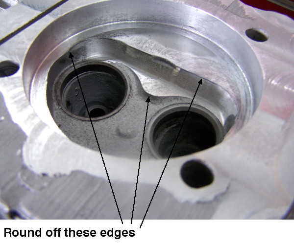
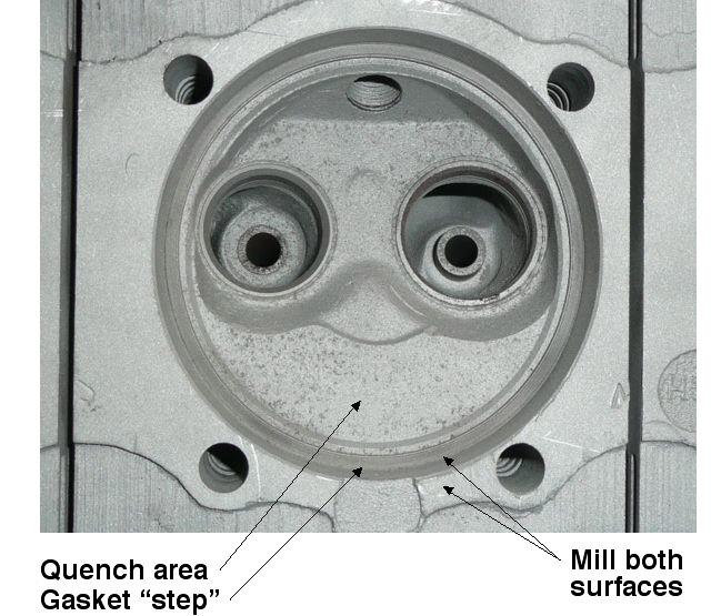
However, if we mill 0.050" off the head to remove this "step", set up the piston so the top is even with the top of cylinder barrel, then use a 0.032" gasket, the two (relatively) cool surfaces so close together reduces the possiblity of detonation and promotes a great deal of turbulence which keeps the mixture even and makes for a better burn. To then reduce the compression ratio, a small amount can be milled off the piston opposite the valves. Most Corvair engines came with a bit less than the rated compression, so a suggested amount to mill off the pistons is about 0.030", resulting in a true CR about 1/2 point higher than stock, but since it is less likely to detonate, this usually works out quite well. When you hear discussion of the "milling off the step" in the chamber, this is what we're talking about. Since castings do vary, it is a good idea to CC the heads, check with your engine builder for more details.
This modification works well on all closed chamber heads, and a set of 95 heads with this modification makes a nice improvement on turbo engines. For 110s, using a set of milled 95 heads with uncut pistons should result in a true 9:1 compression, and be much less likely to detonate. If you don't have any 95 heads, you can have your machinist mill out the "nose shaped" filled in area to reduce the compression back to 9:1. In any case, round off any sharp edges when you're done. Above are before and after photos from Mel Herwald of a 110 head he had modified as described.
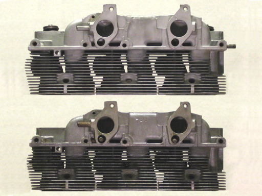
The heads do the bulk of the cooling on the engine (later racing Porsches went to water cooled heads with no fins on the barrels), and the more air you can move over the heads, the better. Further, the castings often have enough flash on the fins that some areas will be completely blocked, especially on later castings as the molds wore. The better a job you do cleaning out the flash, the happier your engine will be. Here are the suggestions I've gotten on tools to clean the fins from VirtualVairs:
If no one has told you yet, the greatest cause of Corvair engine heating is due to casting flash in the fins in the heads. If you can, remove the top and bottom shrouds, and clean out the air passages in the heads. I use a keyhole saw, poke it down through each passage and saw to the end of the slot, turn the saw around and saw to the other end of the slot. It is difficult to do with the heads on, as you have the cyl studs and pushrod tubes in the way, but you can make out. You will see what is supposed to be a large hole through just above the spark plug. It may have a piece of flash passing through the middle of it. Knock it out, and go after it with a 3/8" rat tail file. This hole is supposed to supply the air to cool the top of the combustion chamber. This has three fins that are visible from below, and sometimes have a roof of flash over them, making them totally ineffective. I use a long screwdriver to pry this flash off. You may not be able to work on this because the exhaust manifolds may be in the way. I don't remember this part too well, as I do this with the heads off. This cleaning process is a must for anyone who has an FC or UltraVan. I have both. It will make your engine run at least 50 degrees cooler. From mid-spring to mid-fall, run with the bottom shrouds off.See the Corsa Tech Guide for more info.
Here's a shot of two heads, the top one is after deflashing, courtesy of Roger Gault:
I have read a number of descriptions of setting up rocker arm geometry, this one by Ray Sedman is concise and accurate:
Here is a simple way to get the job done:
[O.K., some may not consider it simple, but you do not need a bunch of other stuff to get the job done :-)]
- Get an off the shelf solid lifter, a SBC solid lifter will do just fine.
- Get or make an adjustable pushrod.
- You have the light checking springs in your head already. Good.
- Put the solid lifter in the engine, bolt the head on lightly, but do no install the pushrod tubes.
- Pick a valve, intake or exhaust; rotate the engine so the lifter is on the heel of the cam.
- Adjust your pushrod so the rocker arm tip is on the lower 1/3 of the valve stem. Or, if you are running roller rockers, adjust your pushrod so the rocker tip is just below the centerline of the valve stem.
- Turn the engine in its normal rotation until you are at full lift. Verify that the rocker arm tip is now on the upper 1/3 of the valve stem or, if you are running roller rockers, the rocker tip is just above the centerline of the valve stem.
- Measure the pushrod length.
- Do the same for the next valve, and then on the other head.
- Measure the test lifter and the lifter you will use in the engine. Adjust for the difference, if any and get the correct pushrod length you need. Note: Each 1/4 turn on the rocker arm stud moves the lifter pocket .0125".
Cheers!
Ray
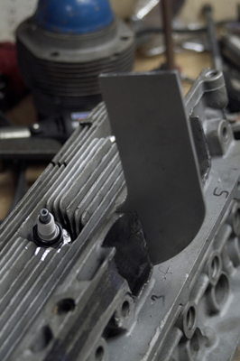
One real advantage to the Corvair's aluminum heads is they can be welded more easily than cast iron heads. Tom Stark is making some radical modifications to a set of heads for his drag car, which currently has a 110 in it. Here are some photos and his description of the mods:
I am building some 140 heads for the car I hope to use next year. I am relocating the spark plugs, and angling them toward the exhaust valve. They now require 3/4" reach plugs. I will be using VW valves, and have a hand made intake on each head. LOTS of welding and machining. I will also be using shaft mounted rocker arms. I have NO CNC equipment, so will have to make everything on a regular Bridgeport. I figure each of the 6 rocker stands will have over 30 machine operations performed to make the bases! As I said, I would really like to have these on the car next year, (with the EFI of course!), and would like it no later than the NECC drags that will be here in 2007. (got to be realistic, there is a LOT of work to do on these, and money to spend also!)
I hope to have my ignition controlled by computer sometime late next week. I am getting rid of the vacuum and centrifugal advance and going for full computer advance based on rpm and map. I checked my timing with a light, just to see where I am, and I have 41 degrees advance, with 21 initial and NO spark knock! It is all in by 2400. So I will program in more advance in higher rpms. I think I can go has high as around 48 under full load. Right now under cruise I am at 68 degrees! Really blew my mind. And I know the readings are right as I TDC'd the motor when I got the new balancer.
I hope to have the new heads, and the EFI get me into the 14's. I will need a new clutch also. I was talking with Detroit joint clutch and gear, and the racing guy there told me about a clutch they have that is kind to the flywheel and pressure plate, and has a consistent coefficient of friction up through 450 degrees. They can make something up custom for me.
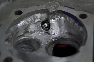
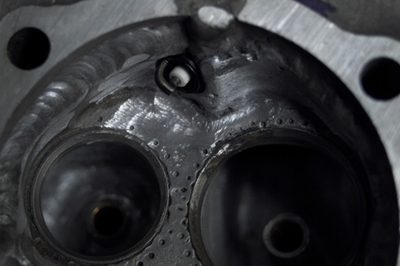
Here are some photos of the heads "In production." They are a bit rough right now, but when finished, they will look great. These photos will give you an idea of what is going on.
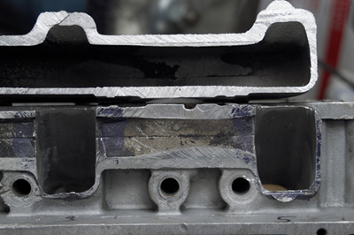
I have a bit more welding to do in the plug area. We had no way to know how much to add, so we just sort of guessed. The aluminum is a little short in spots, so we will add a little more. I also decided, since I have to add more to the threaded area anyway, I may as well get a little more aggressive and push the plugs right up against the roof of the chamber. The head gasket area has been welded to make it work with early jugs. I know I could use shim stock, but I am just not that comfortable doing it that way. Plus, this way I get good alloy in the head gasket register.
I have no idea what compression ratio I am going to wind up with. I know with my 110 heads I opened up the chambers to reduce it to 10.5:1 I will not worry about compression with these heads. I am running 41 degrees timing and it is all in by about 2400. NO knock! I use 94 octane gas with octane booster, (I use 1/2 or slightly less than the recommended amount of booster). Now that I have my computer to run the ignition and will no longer use vacuum or centrifugal advance, I will try mapping the timing up to about 46 or 48 degrees under full load. (Under cruise right now I am running 58).
I will keep you posted about these heads. Next year would be the soonest I will be running them. The guy I am having do my seats is about the most expensive guy on the planet. I know I can get the job done for 1/2 what he wants, but I also know that NO ONE could do the job any better than he can. I figure if he can make those top fuel heads live, he can make a Corvair head live!
Tom
You can see photos of Tom's car on his web site: http://www.absolutetops.com/Corvair/Corvair.html.