
Custom Search


Converting a Corvair to EFI isn't a weekend project, but Craig has laid out the process in good detail, other than welding the injector bosses each step of the project is doable by many enthusiasts. Click on any of the photos on this page for the larger version.
The story of the Tuned-Port Corvair begins with a little history...
In 1985, Chevrolet introduced "Tuned-Port Injection" on the Corvette, and Camaro 305 and 350 Engines.
At the same time, selected "Sporty" V6 versions were also introduced on Chevrolet and Pontiac vehicles such as the Fiero GT.
These systems featured long intake runners to improve low rpm torque, individual injectors in each intake port, and self tuning corrections using an oxygen sensor in the exhaust. Not long after their introduction, the aftermarket began to provide the products and services needed to install these V8 engines and systems in custom vehicles.
While Milt Binion and others had adapted EFI hardware from other vehicles to the Corvair, it seems that no one had tried to adapt a Corvair to a modern, self-diagnosing, closed-loop feedback system like the Tuned-port system. There were many naysayers who said it would never work, nevertheless, the Tuned-Port Corvair fuel injection conversion was completed in 1999 and has been going strong ever since.
The plan was to adapt a complete system from a 6-cylinder donor which similar displacement and horsepower; this to minimize the cost and need for re-programming the ECM to match the engine. Why not take advantage of the millions of R&D dollars spent developing and testing these existing systems?
The GM 2.8 MPFI or Multiport Fuel Injection, GM's 6-cylinder version of Tuned Port Injection, and Ford's 2.8 V6 systems both were suitable candidates. The GM system was selected because of better scan-tool diagnostic output and more available conversion information.
Use of stock programming was a central part of the project for several reasons. Vendors familiar with V8 TPI applications were plentiful, but those vendors were not familiar with the MPFI V6 system. Very few GM ECMs had been "cracked" for DIY reprogramming and besides, re-programming is a trial and error process that's never really done. While it's usually an afternoon's work to get a reprogrammed ECM running", a complete mapping for all situations takes about 200 hours. Since the donor engines have very similar displacement and power output, it's likely that either the Ford or GM system would have worked using stock programming.
In the GM family, the Fiero 2.8 V6 was selected due to it was the simplest of the MPFI* line-up; it used a distributor, not coil packs, had no knock sensor, and used a Manifold Air Pressure (MAP) sensor rather than the trouble-prone Mass Airflow Sensor (MAF). Now that the concept has been proven to work, there's no reason to avoid these components or more complicated MPFI configurations.
The installation process involved quite a few mini-projects. The most involved projects were the modification of the distributor and cylinder heads.
Here's the project list...
* MPFI, "Mulit-Port Fuel Injection" is GM's generic name for this system. "Tuned-port" is a marketing label for Chevrolet V8 versions of MPFI.
What follows is an overview of each of the individual installation projects required to make a complete system:
 The tops of the cylinder head intake logs were milled at a 45-degree angle to create oval openings for the injector bungs.
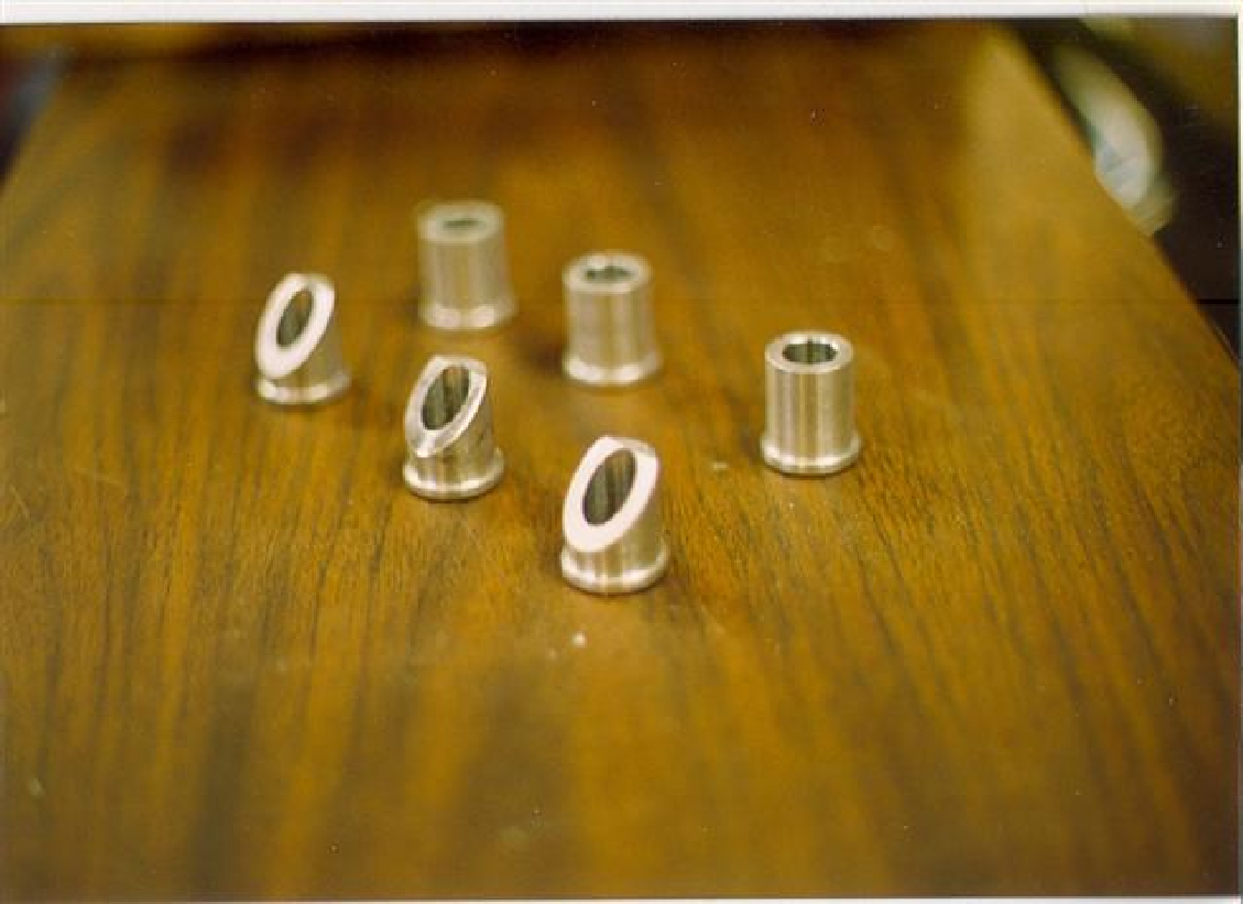 The underside of each bung was milled at a 45-degree angle so the inside of the intake manifold remained unobstructed.
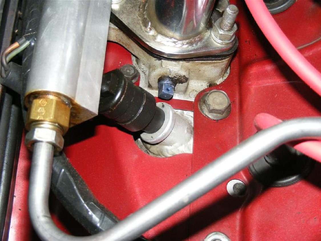 The machined bungs were heli-arc welded to the manifold. During welding, a fixture insured that the bungs were aligned with the intake valves.
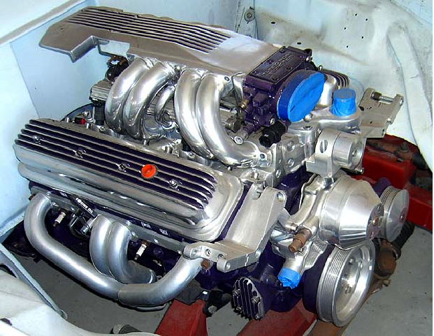
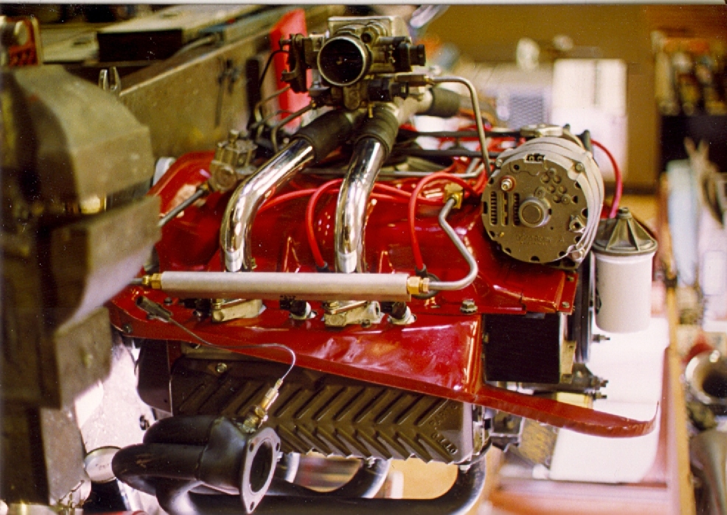
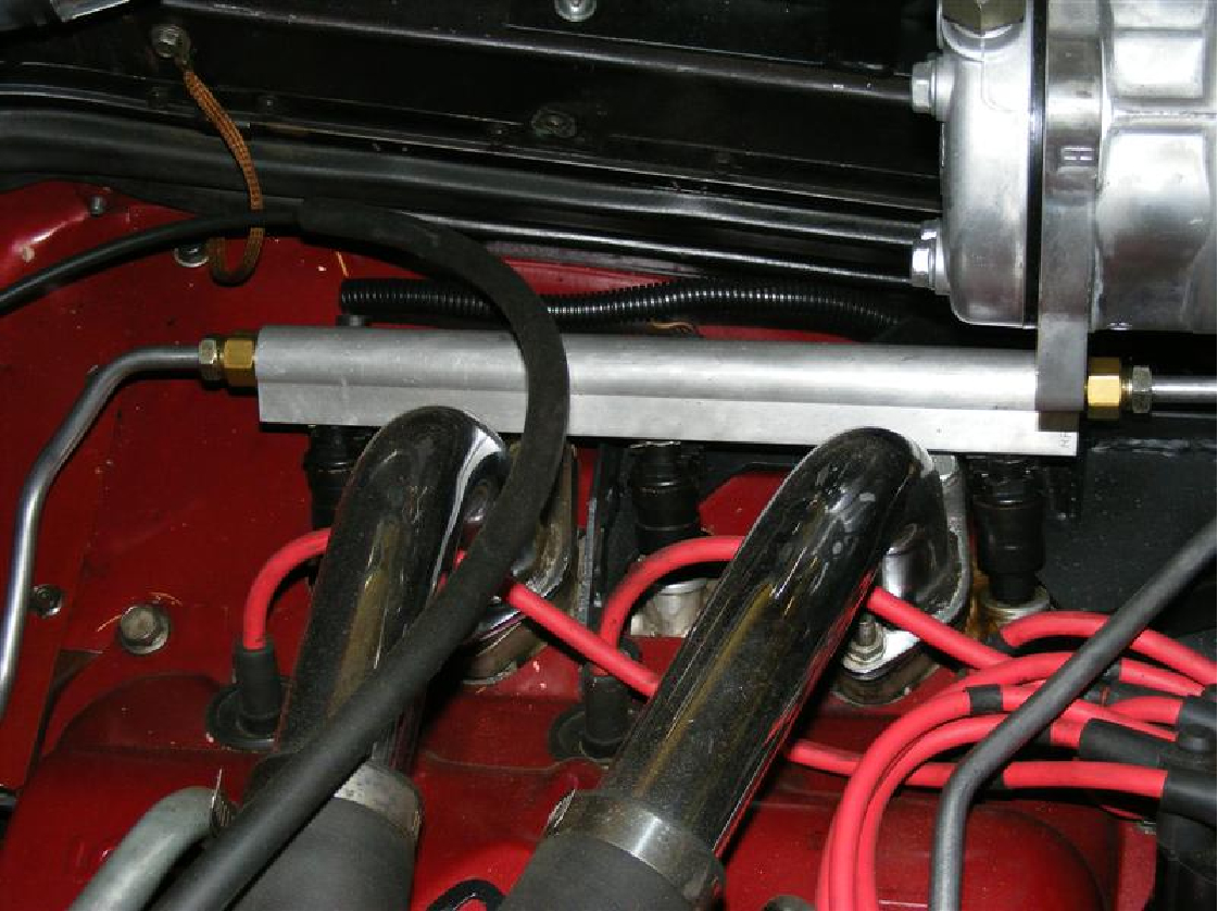 The only OEM fuel rail with Corvair's bore spacing was the big-block Chevy and those rails were hard to come by. Fortunately Accel sells blank fuel rail by the inch and injector bungs in sets of eight. The blank rails were drilled and tapped for injectors and supply lines. The fuel rails are secured to the cylinder head with small aluminum straps.
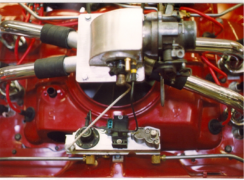
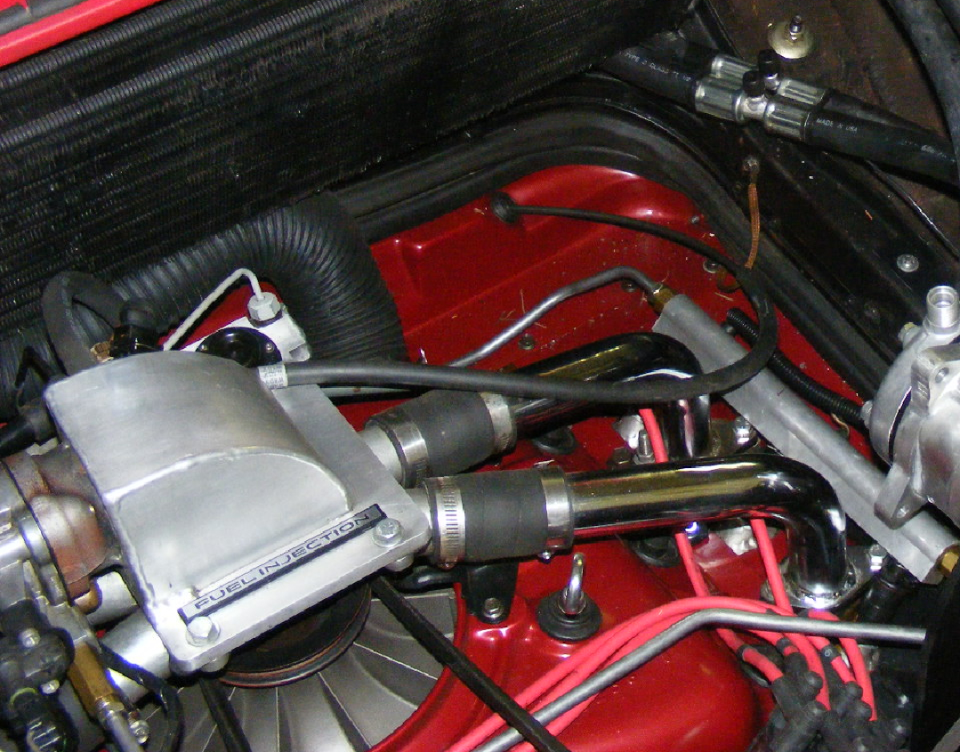
 The Fiero's original V6 fuel rail, visible in the foreground of the photo, is mounted at the front of the engine using the original Corvair balance tube mounting points. Also on the original fuel rail; the fuel supply for the cold-start injector, fuel pressure regulator, MAP sensor, pressure stabilizer, and pressure test port. Four original injector holes were welded shut and two were tapped for fittings to the new rails.
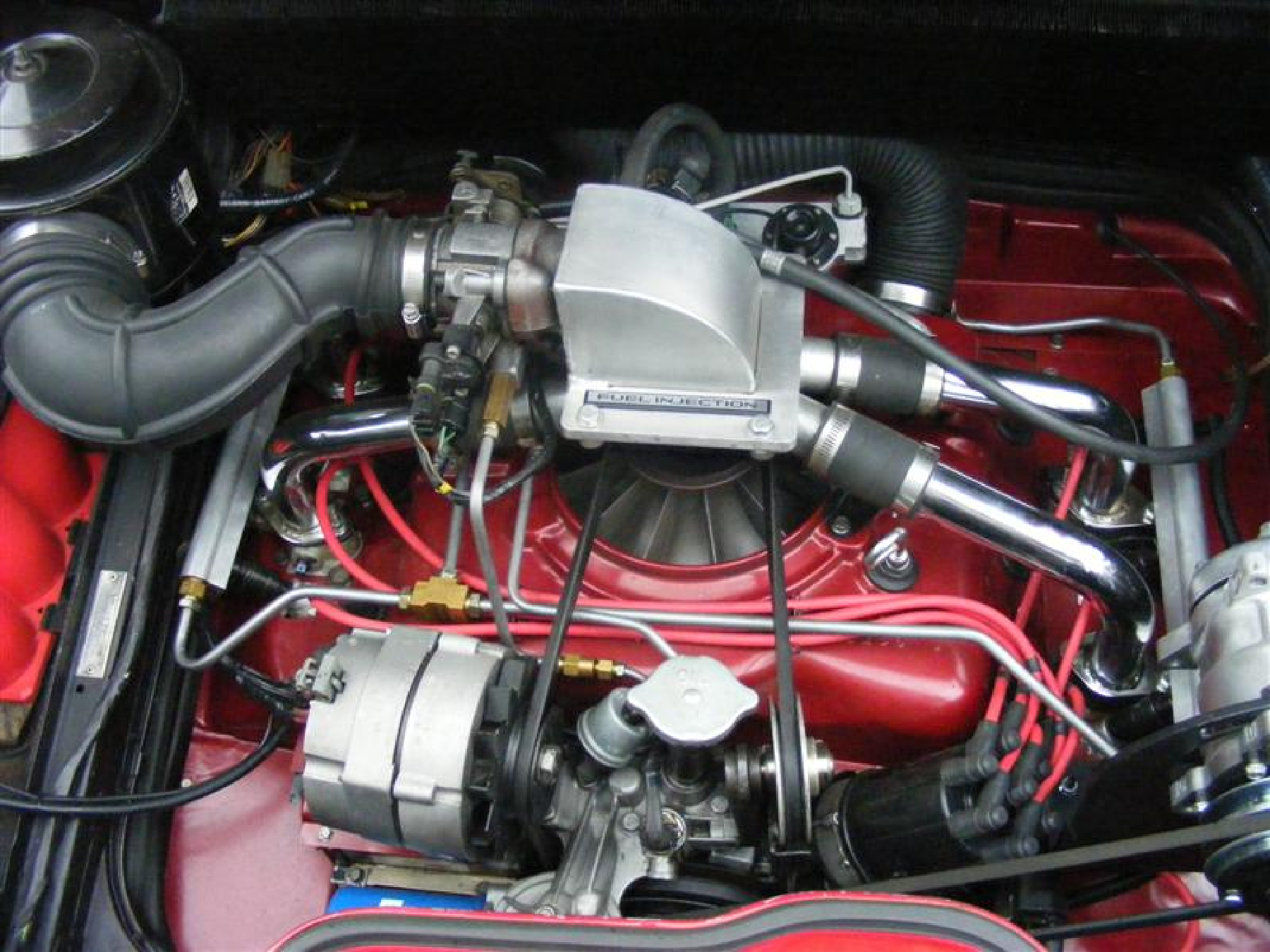
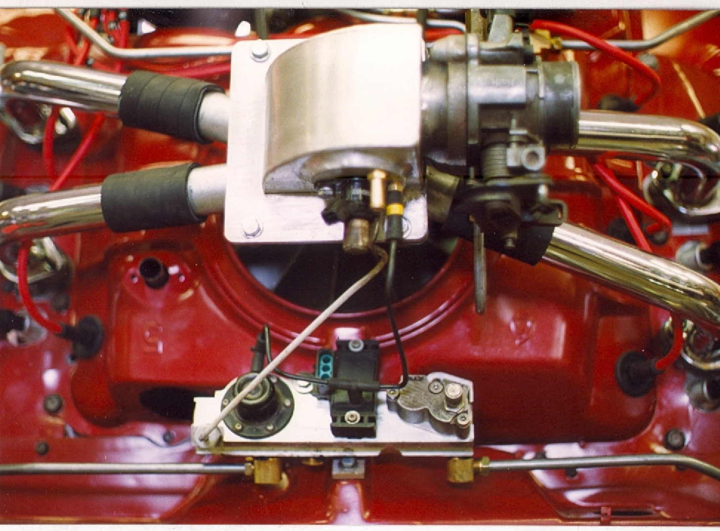
At the front of the intake adapter are the cold-start injector, MAP sensor fitting, and a fitting for the idle air inlet.
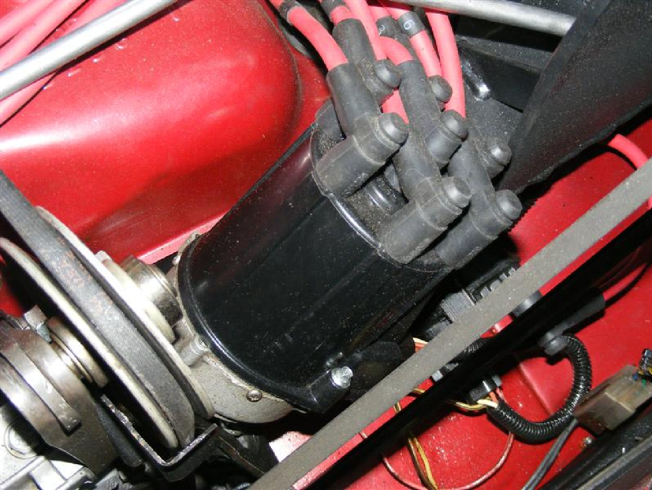

A mix of Corvair and Fiero, the lower portion of the Corvair shaft is mated to the upper section of the Fiero shaft. The bottom of the Fiero distributor bowl was machined smooth; it's screwed to an aluminum ring mounted in the Corvair's distributor bowl. The HEI ignition coil is mounted in the same place as a regular Corvair distributor.
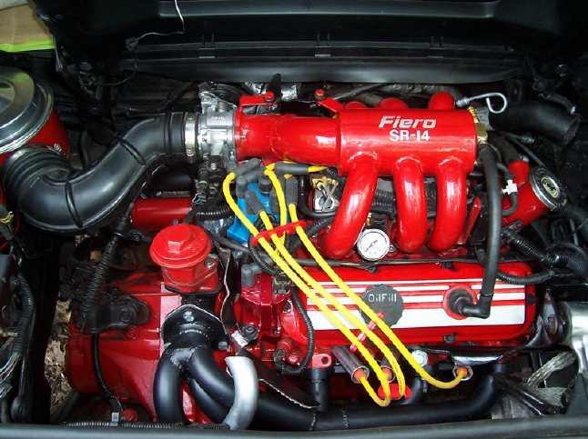
An aftermarket 140-4-bbl adaptor and fabricated air box distribute air from the throttle to the four cylinder head air intakes. The throttle flange from the Fiero intake is welded to the air box. To prevent throttle freezing, the original throttle included passages for circulating warm coolant, Instead of coolant, a turbo oil tee provides warm motor oil for the throttle while return oil dumps into the oil fill tube.
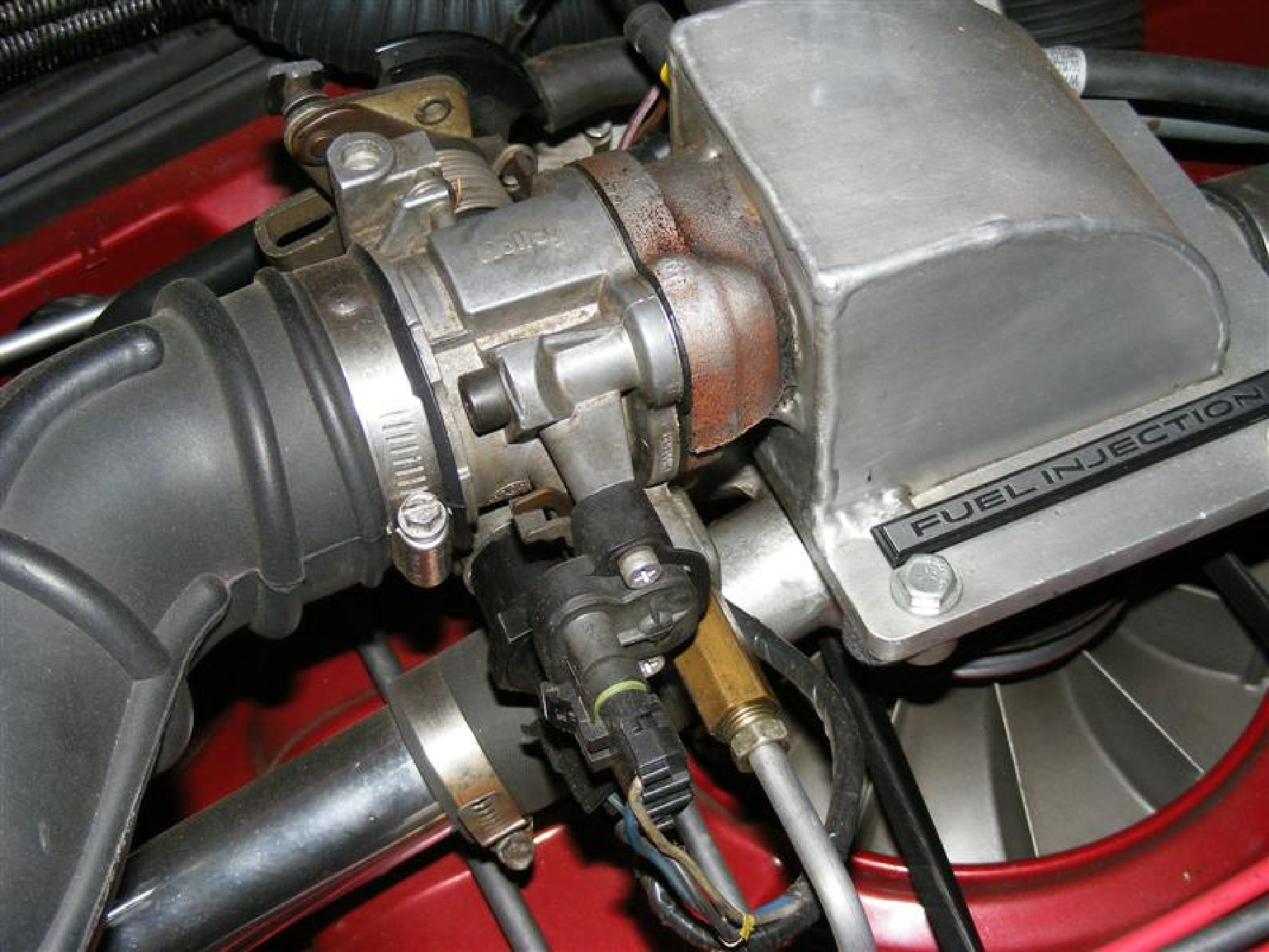

The stock Fiero air cleaner fit well but the Intake Air Temperature sensor was relocated to provide clearance for the deck lid support. Intake noise is effectively muffled by the thick rubber intake duct.

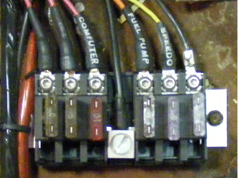
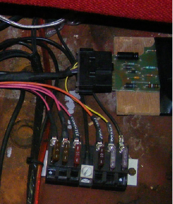
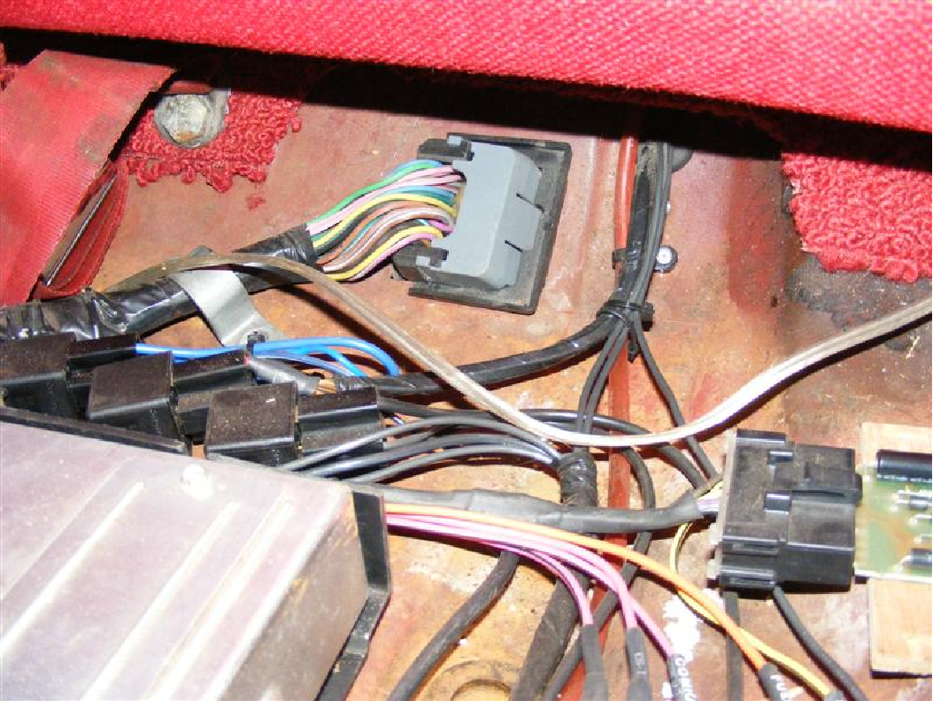
The stock Fiero ECM, with original 2.8 V6 programming, is located under the rear seat, as are relays for fuel pump & A/C compressor. The auxiliary fuse panel includes circuits for injectors, ECM, fuel pump, speedo buffer, and O2 sensor
A heated oxygen sensor is installed in left exhaust header. This O2 sensor is rather distant from the cylinder head and early testing revealed that the original unheated sensor would cool off and stop working at idle speeds. Upgrading to a heated sensor cured the problem.

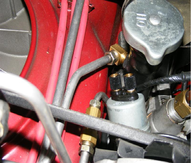
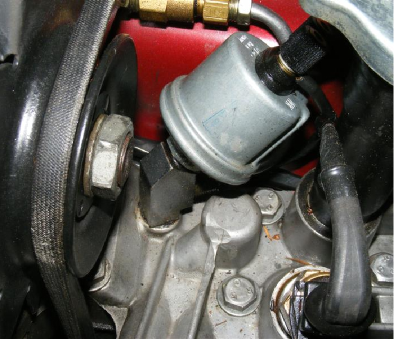
This sensor is mounted in the original fuel pump mounting hole where it senses oil temperature instead of the usual coolant. As the engine warms, there's less and less run-time for the cold start injector. When the engine is warmed up, there's no flow at the "cold-start" 7th injector.
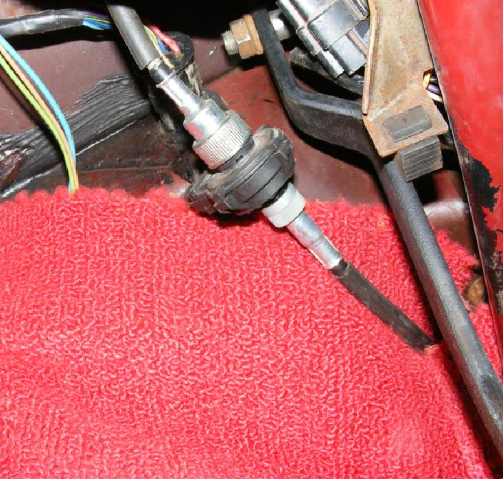
When the vehicle is stopped, the ECM uses the idle air motor to control the idle speed so the ECM uses a vehicle speed sensor to know when the vehicle is moving and when it's stopped. To install the VSS, the original speedometer cable was taken to a speedo shop where it was cut and fittings were installed to accept the inline vehicle speed sensor. The sensor output goes to a "VSS buffer" module that's next to the ECM.
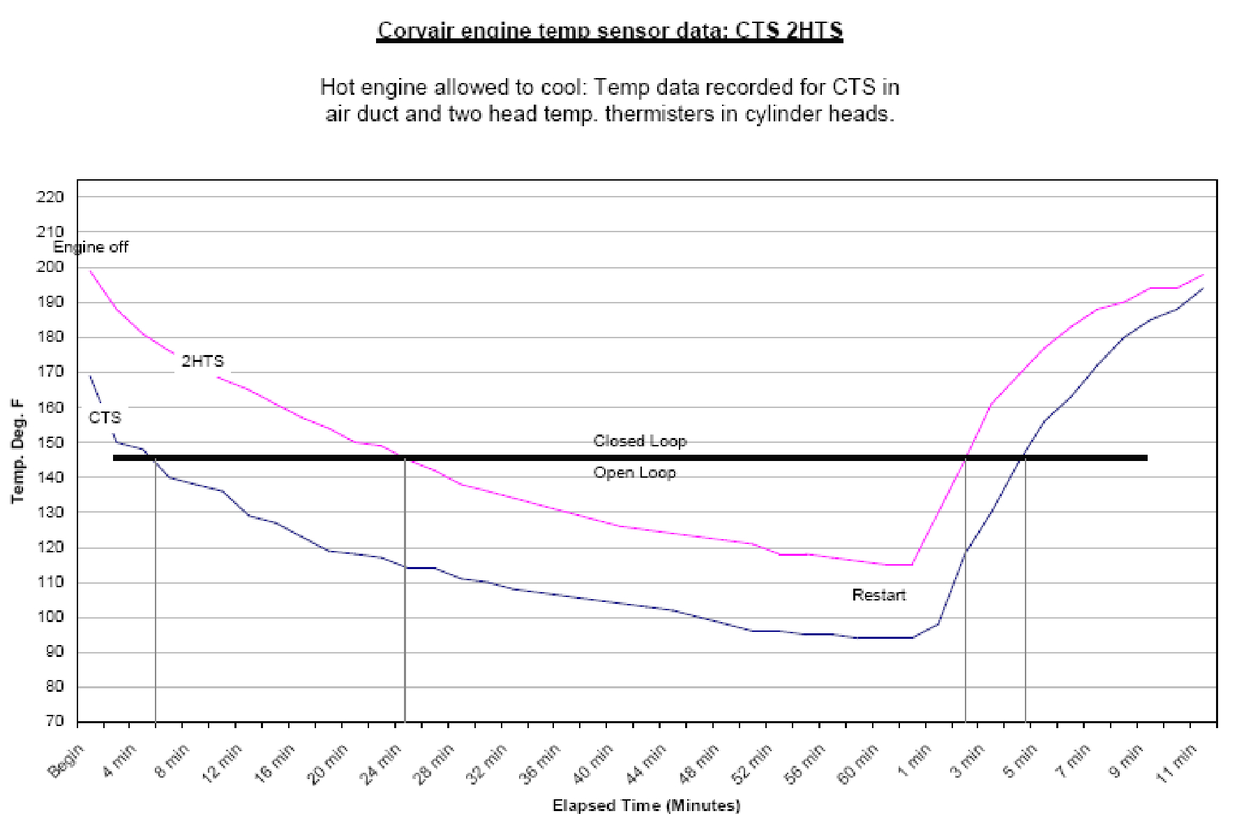
The coolant temperature sensor is what's called a "Primary" sensor; � it has a huge effect on the fuel delivery so it has to accurately reflect engine temperature. At first, the Fiero's coolant sensor was mounted in the front of the lower air duct. Since duct air is regulated to 195 degrees it should have been about right but in practice it wasn't a good solution. While cold-start, warm-up and cruise were fine, hot-restart wasn't very good. The sensor, being mounted in free-air, cooled off quickly and causing over-rich restarts, black smoke, and embarrassment. After some experimentation with factory head-temperature thermistors, a better solution emerged: two factory thermistors in parallel. This unorthodox approach yields good cold starts, accurate transition timing to closed-loop operation, a very acceptable "195 degree" cruise temperature reported the ECM and even a reasonable temperature for over-temperature lighting of the check-engine light.
Below are graphs of normal engine temperatures and sensor ohms presented to the ECM. Bold values are the normal operating temperatures and the related sensor output for each type of engine.
| Water cooled engine temperature | CTS ohms |
| 42 | 6330 |
| 100 | 1800 |
| 125 | 1077 |
| 150 | 658 |
| 175 | 419 |
| 200 | 266 |
| 225 | 179 |
| Corvair head temperature | 2-parallel thermistor ohms |
| 42 | 4991 |
| 100 | 2250 |
| 150 | 1110 |
| 200 | 585 |
| 275 | 265 |
| 300 | 210 |
| 325 | 160 |
| 400 | 80 |
Below is a comparison of the duct mounted CTS and the cylinder-head mounted thermistors. The CTS temperature drops quickly in the first five minutes after engine shut-off and reports a cool temperature that results in poor hot-restart.
The EGR system has been electrically bypassed. The ECM commands the EGR open by grounding its' solenoid coil. The ECM then checks the valve by looking for a ground from a pressure switch on the EGR valve output. By connecting the ECM command signal to the ECM sensor line, the ECM will see a ground every time the EGR valve is commanded ON. While this solution was good, the decision to eliminate EGR was not. EGR suppresses spark knock at mid-range throttle openings. Since this engine had some spark-knock, the timing had to be retarded a bit and this caused a slight loss of power.
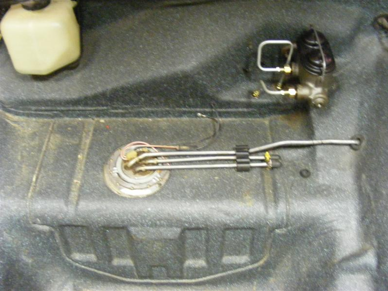
New steel hard-line runs from the in-tank pump to the fuel rails. Excess fuel in the rails is piped to the pressure regulator where it sends excess fuel back to the tank through the original fuel line. The pump mounting ring was grafted-in from an S-10 blazer tank. While the pump is capable of 90 PSI, the regulator spills most of the fuel back to the tank and maintains 35 to 45 PSI in the fuel system.
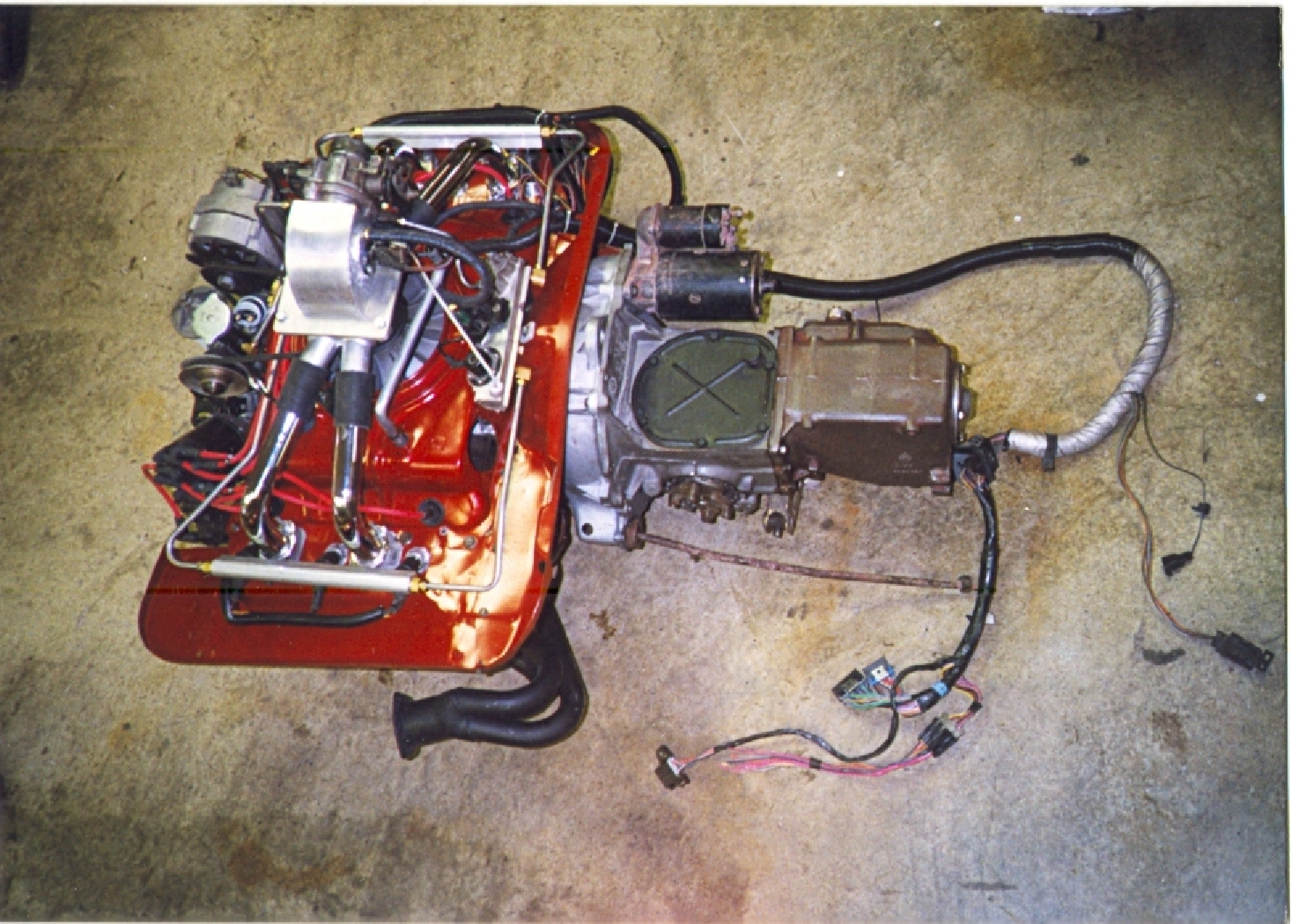
The stock V6 Fiero harness was widened to accommodate the Corvair flat six. Several quick disconnects were installed where the cable enters the engine compartment to facilitate engine removal, The Fiero harness included a hard grommet that protects the harness where it passes through the firewall, er, rear seat bulkhead.
Originating from the bell-crank at the rear of the undercar tunnel, the long stock Fiero throttle cable is routed into the engine compartment where it connects to the Fiero throttle. Just for fun, the cable and grommet come through the shroud at a flat area designed for the automatic transmission dipstick.
The initial problems: rich hot-restart, cool oxygen sensor, and poor idle due to lack of VSS have been solved. Characteristic of early MPFI systems, the "idle strategy" isn't rock solid, but idle is correct 90% of the time.
Overall, the system works very well. The 52mm throttle offers the same surface area as the stock 140 carburetors, but should flow better due to lack of any choke equipment in the air horn. The system has very good low-end torque but there's no significant power increase. Highway fuel economy is excellent - nearly 30 mpg.
Now that the concept has been proven, a next step would be to fit an MPFI system with a mass airflow sensor, EGR, and distributor-less ignition.